Volscan Profiler and Ceramscan troubleshooting
Having problems with your Volscan Profiler or Ceramscan? Most issues can be resolved quickly with a few simple checks.
How to check your Volscan Profiler / Ceramscan
The checks below are grouped by problem area so you can go straight to the one that matches your symptom.
First line checks (start here)
- Power cable firmly connected to the IEC mains inlet (labelled Power In) on the instrument and to a working, earthed mains outlet.
- USB cable connected from the Type-B socket on the side of the Volscan Profiler/Ceramscan to a USB port on your PC.
- Use only the cables supplied by Stable Micro Systems. Third-party cables can prevent the system from working properly.
- Ignore the Ethernet socket and the second USB Type-A connector on the instrument. These are reserved for service use and should not be connected.
The Emergency Stop button on the front of the instrument cuts mains power when pressed and latches in place. If your instrument shows no signs of life:
- Look for the red mushroom button on the front of the cabinet.
- Twist the button clockwise until it pops out.
- Switch the instrument on at the power switch and allow it to boot.

The instrument will not start a scan unless the door is fully closed. The door is interlocked for laser safety, so the laser is automatically switched off when the door is opened. If a scan refuses to start, check the door is firmly shut and the latch has engaged.
When the instrument is powered on correctly, the lights inside the top of the cabinet should be illuminated. After switch-on, you will hear the laser carriage move down to the bottom stop position; this is normal and is how the instrument calibrates its vertical position.
The status box in the software should change from "Booting" to "Online" within a few seconds of the instrument finishing this start-up movement. Common status messages and what they mean are listed in the user manual under VSP Status.
The Load Cell and electronics need time to stabilise after switch-on. We recommend allowing 30 to 60 minutes warm-up before performing any tests, and especially before any calibration. This is the single most common cause of weight drift reported by new users.
Update your firmware and software
The latest Volscan Profiler/Ceramscan software is available free of charge from the software updates page. To check what version you are currently running, click Help > About within the software.
If you have not updated your software for a while it is highly likely that your software issue has been identified, fixed and the latest version will have resolved it.
The latest firmware is supplied with the software installer.
You can check what version you have by clicking on Help > About:
Once the new software is installed:
Run the Volscan Profiler/Ceramscan software with the instrument connected and switched on.
Go to Tool > Scanner Utilities:
Then click the update firmware menu command (as highlighted in the next image) and select the firmware file to use for the update.
This is normally located in the firmware subfolder in the location that you installed the Volscan Profiler/Ceramscan software. Once you have selected this file, the firmware will be downloaded to your instrument and then automatically re-programmed. You will see the progress of this operation displayed.
Three calibrations affect volume accuracy and must be run in this order: Weight, then Zero Height, then Laser Distance. All three are accessed from Tool > Scanner Utilities > Procedures.
We recommend recalibrating after any software or firmware update, after the instrument has been moved, and otherwise on a regular basis suited to your usage pattern.
For verification, Stable Micro Systems supplies a Calibration and Verification Rod (VSP/CVR) as an optional accessory. The rod is supplied with a calibration sheet and a software macro that prompts you for the relevant values, scans the rod and confirms whether the measured volume falls within tolerance.
Verifying the volume measurement
Stable Micro Systems provide a Calibration and Verification Rod (VSP/CVR) as an optional accessory to the Volscan Profiler/Ceramscan. By placing this ‘known volume’ into the instrument and performing the following procedure the instrument can verify if it is correctly reading volume, height, width and length.
The VSP/CVR is a precision-made ceramic cylinder with special mounting pins fitted in each end.
Remove the three pins from the Product Support to expose the socket in the top of the Product Support.
Volscan Profiler VSP/CVR
Performing a volume verification
1. Remove whichever product support you have from the instrument and get the screwdriver ready as shown in the next images.
Remove the three pins from the Product Support to expose the socket in the top of the Product Support.
To do this, turn the product support upside down and locate the screw used to secure the pins. This is at the end of the central shaft. Using the screwdriver provided remove the pins by placing the screwdriver down the hole to engage the screw and then turning in an anti-clockwise direction until the pins can be removed.
or
Take care not to lose any of the Product Support components.
2. Move the arm to the top of the instrument.
3. Now replace the product support back into the Volscan.
4. Next locate the bottom end of the Calibration and Verification Rod indicated by the drive pin.
Locate the drive pin into the product support. Ensure the drive pin is fully engaged in the hole designed for it.
5. Carefully lower the instrument arm to engage the top ball-ended pin of the Calibration and Verification Rod into the Top Pin Bearing in the end of the arm.
The arm should just engage with the pin enough to hold the ball in place, ensuring the metal guide bar is higher than the ball.
6. Now that the Verification Rod has been placed into the instrument close the door and open the software.
Next ensure the CVR Volume Verification macro is selected in the macro list as shown below. If not, then click on the list to drop it down and select the macro from the options in the list. Click the Run Macro button to run the macro and begin the verification procedure.
The macro will prompt for a number of values from the Calibration sheet that was supplied with the rod.
1. Enter values, starting with the rod length as shown below:
2. Click on OK to proceed. Next the top diameter:
3. Lastly the bottom diameter:
Following the entry of all the rod information, the software calculates the expected volume and does a zero-height calibration from the bottom lip of the rod.
Once the zero-height calibration is complete, the rod is scanned as shown below:
This process will take around 6 to 7 minutes.
After testing the scan of the rod is examined at a position 5mm above the lip and 5mm down from the top to validate against the measurements taken of the rod using the calibrated callipers.
Once fully scanned the macro will measure the diameters and length, then calculate the expected volume and verify the scan against the numbers on the VCR sheet. This may take a few seconds to complete but once done it will produce a pass/fail report which will be shown on screen.
Once the scan is complete, the scan is compared against the pass and fail limits. The outcome of the verification is then shown:
A report is produced with more detailed information of the verification as shown below which can be saved or printed for your records:
Connection and start-up problems
Check the cables and emergency stop button isn't pushed in – see above checks for detail.
Work through the following in order:
- Make sure the Volscan Profiler/Ceramscan is plugged in and switched on. The lights inside the top of the cabinet should be illuminated.
- Make sure the USB cable is connected at both the instrument and the PC.
- Check that the Emergency Stop button is not pressed in.
- Make sure the USB drivers are installed correctly. There is a document in the USB Drivers folder where the Volscan Profiler/Ceramscan software is installed, with full instructions.
- Try a different USB port on the PC, ideally a port directly on the motherboard rather than a hub.
- Restart the instrument and the software, then try again.
This means the instrument is either not powered on or is not communicating with the PC. Follow the same steps as above for "The Volscan system has not been detected".
Close the door fully and ensure the latch engages. The instrument will not run while the door is open.
- Check the Emergency Stop button is released.
- Check the mains fuses in the appliance mains inlet (these are the only user-serviceable items). Replace only with the approved type: T3.15AH250V (3.15 Amp). Spare fuses of this type are supplied with the instrument.
- If the instrument is still unresponsive, contact Stable Micro Systems or your distributor.
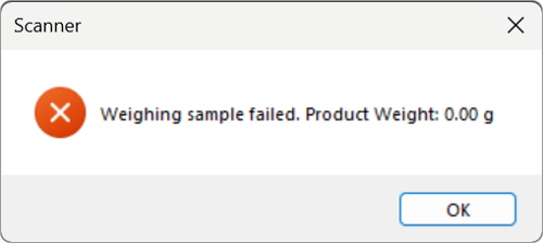
With Auto-weigh enabled, the software will not start a scan if the measured sample weight is zero or below. An error message is displayed instead.
Remove the product and tare the product support again, including the top pin if you are using one.

Scan quality problems
An example of a spike in 2D and 3D is shown below:
A spike on a 2D or 3D scan is almost always a "laser error", caused by a brief loss of valid distance data from the laser sensor. While this rarely affects the calculated volume by any meaningful amount, it can look unsightly.
To remove laser-error spikes:
- Open the affected scan.
- Toggle on Edit > Filter Laser Errors. The software will replace each error point with the average of its neighbours.
If the result is not quite right, fine-tune the behaviour under File > Global Options:
- Filter Percentage sets how big a change between adjacent points counts as a spike.
- Minimum Filter Offset (mm) prevents very small changes on small-radius products from being flagged.
- Number of Points to Filter Over lets you handle spikes that span more than one point (up to 10).
You can return to defaults at any time using Reset to defaults.
Stray reflections from sharp edges or shiny surfaces at the very top or bottom of the product can produce small spikes. Use one of the following post-scan tools (right-click on the 2D scan):
- Remove Reflections: automatically detects and smooths spikes at the ends of the product.
- Smooth Selected Data: ramps the polar lengths between two chosen points.
- Flatten Selected Data: forces a straight line between two chosen points.
All three actions can be reversed using Undo.
This is usually caused by laser reflections around a sharp corner or reflective surface, and it most often happens when the top supporting pin is not in use (for example, on solid samples).
Place the supplied top pin through the top arm support and rest the tip centrally on the top of the sample. This breaks up the reflection and gives a clean scan.
Slice data can appear to be missing for a few reasons:
- Sample mounted off-centre: the laser cannot see part of the sample as it rotates. Re-mount the sample concentrically on the central pin or platform.
- Sample protruding outside the operating window: any part of the sample (at any height) that enters the shaded area marked on the instrument base will not scan correctly.
- Step size too coarse: increase resolution by selecting a finer Vertical Step Size (down to 0.5mm) in the New Scan settings. The trade-off is a longer scan time.
- Heavy laser-error filtering: if you have aggressive filter settings or are filtering many points, genuine data near a feature may be smoothed away. Reduce the Number of Points to Filter Over and re-test.
If slices are still missing, save the scan file and contact technical support.
Four sample properties affect scan quality: surface texture, transparency, colour, and the angle at which features present to the laser. Each is covered in Difficult sample issues below, with the recommended fix.
Difficult sample issues
Some sample surfaces are more problematic for the laser. If scans look distorted, noisy or contain unexpected volume, the surface itself may be the cause.
Products must also be of a “friendly” shape for the laser to successfully scan them. For example, a mug handle would be filled in by the laser as the laser can only draw an outline around the perimeter of the shape – it would turn the handle into a solid shape on the side of the cup. Samples that might be difficult to scan include crescent shapes and samples with voids or holes.
Dark surfaces absorb more of the laser's light, so less is reflected back to the sensor. This can produce noisy or unreliable distance readings, particularly on contrasting samples that are partly light and partly dark (the laser sees the two areas very differently).
Things to try:
- Lightly mist the sample with a matt starch-based spray to give the laser a uniform, diffuse surface to read. This is the most reliable fix.
- Reduce the rotation speed and use a finer step size; this gives the laser more time to acquire each reading.
- Check that Filter Laser Errors is enabled (under Edit > Filter Laser Errors) so any individual error points are smoothed.
Highly reflective surfaces send the laser light off at angles other than back to the sensor, producing distorted or missing data, especially around sharp edges.
The simplest fix is to spray the sample with a matt starch-based spray before scanning. This gives a diffuse, non-reflective surface and preserves the sample shape. Many users keep a can of starch spray next to the instrument for exactly this purpose.
If the sample is transparent or translucent, the laser cannot reliably tell where the surface actually is, because some of the light passes through and reflects from inside the sample. This is particularly common with thin films, gels and some organic products with translucent skins.
A light coat of matt starch-based spray on the surface usually resolves this. For samples where spraying is not acceptable, the Volscan Profiler/Ceramscan may not be the right instrument for accurate volume measurement.
Strongly contrasting colours, particularly black-and-white patterns, are absorbed differently by the laser and can create the appearance of false volume in the scan. The effect is most pronounced where the colour boundary is sharp.
Where possible, scan a single-colour version of the sample, or apply a uniform matt starch coating before scanning.
The laser can only see surfaces it has a direct line of sight to. Cracks, crevices or undercuts that lie parallel to the laser beam are read as a flat surface, not as a recessed feature. This is a fundamental limit of the line-of-sight measurement method, not a fault.
Where possible, reposition or reorient the sample so the feature is presented to the laser more obliquely. Sharp horizontal "spikes" or thin horizons on the sample can be similarly difficult; spraying with matt starch can help here too.
The Volscan Profiler and Ceramscan treat the centre of rotation as the zero position for radial displacement, which makes it the minimum measurable distance. Where a sample contains a void, the laser cannot return a measurement from behind the centre of rotation.
The software fills the void by drawing a straight line from the centre of rotation to the last correctly measured point on the sample surface. Voids and holes are therefore reported as solid, as shown in the doughnut and banana examples below.
Samples of this type require the Skewer supplied in the Universal Product Support kit.
Rotate the sample and re-mount it so the dip is presented to the laser at a different angular position. This improves the measurement across the top surface.
Yes. Sharp horizontal surfaces, spikes and very narrow crevices can distort the laser reading, because the laser reads a feature lying parallel to its beam as a flat plateau rather than a recessed or protruding detail.
The spark plug shown below is a typical example. Scan quality improved once the polished surface was sprayed with matt starch to reduce reflectivity.
Where possible, reorient the sample so the feature is presented to the laser more obliquely.
The laser searches for the product before starting the scan, and will not register a product whose diameter is below the Product Detection Radius. On thin samples this can cause the scan to start below the true top of the product.
Reduce the Product Detection Radius in File > Preferences > Global Options. The minimum value is 0.5mm. Alternatively, change the Start scan at option in the New Scan window.
To view the options of sample mounting go to the Volscan Accessories page.
Sample size and weight limits
Make sure your sample fits within the operating window of the instrument and within the maximum weight. The shaded grey area marked on the instrument base shows the operating window in plan view; nothing should enter that area at any height during the test.
| Specification | VSP600C | VSP300C | Ceramscan |
|---|---|---|---|
| Maximum sample diameter | 380mm | 190mm | 190mm |
| Maximum sample height | 575mm | 275mm | 275mm |
| Maximum sample weight | 3kg | 3kg | 3kg |
If a scan is under-calculating volume and the sample is close to these limits, check that no part of the sample swings outside the shaded operating window during rotation. Even a small overhang on a wide sample can move outside the laser's measurement range.
Using a sample of known density, the instrument measures down to 20mm³ within ±1% volume error, and down to 10mm³ within ±2.5%. For reference, 20mm³ is equivalent to a sphere of approximately 33.6mm diameter and 10mm³ to a sphere of approximately 26.8mm diameter.
Accuracy will be lower than this for most real samples, particularly those with irregular shapes or difficult surfaces.
There is also a lower limit set by product detection. The laser will not register a product of less than 5mm diameter when searching for it at the start of a scan, which can result in part of the sample being missed. Reduce the Product Detection Radius in File > Preferences > Global Options to improve this. The minimum value is 0.5mm.
For small or solid samples that cannot be mounted on pins, two options are available:
- The Product Support for Disposable Inserts (VSP/PSD) uses circular disposable inserts held magnetically to the support. The sample is adhered to the insert with double-sided tape, blu-tack, glue or, for ceramic samples, SIKA adhesive. This support is supplied as standard with the Ceramscan.
- The Weighted Sample Support (VSP/WSS) supports the sample from above using a weighted shaft and a small glue dot. A choice of caps and additional weights is included.
Volume measurement problems
The most common cause is off-centre mounting:
- The product must sit concentrically on the loading pins or platform.
- Pay attention to the shaded area marked on the base of the instrument. The sample must not enter this area at any height during the test.
Other things to check:
- Is the Zero Height Calibration up to date? Run it again, especially if you have changed product support platforms.
- Has the Laser Distance Calibration been performed recently?
- Is the correct Product Support diameter selected during laser calibration? The diameter is printed on the label around the bottom of the support.
Temperature changes during the day can produce a small amount of drift in the laser measurement. To compensate:
- Open File > Preferences > Global Options.
- In the laser calibration mode dropdown, select Auto if you are using the white-ringed product support, or On if you are using an older black product support.
In Auto mode, the software performs a quick laser calibration before each scan when a white-ringed support is detected. In On mode, it does this for every scan regardless of support.
Scan a Calibration and Verification Rod (VSP/CVR) and run the supplied verification macro. See Check your volume calibration > Verifying the volume measurement for the full procedure.
If you do not have a VSP/CVR, contact your distributor to discuss the best verification approach for your application.
Weight measurement problems
Most weight spikes come from one of the following:
- The top pin is not tared before the weighing step. Make sure the top pin is in place and tared if you are using auto-weigh.
- Vibration or knocks to the bench during weighing. Move the instrument to a sturdy, isolated bench out of direct draughts.
- A loose or sticking top pin transmitting force into the load cell. Check the pin moves freely in the arm bush.
- Allow the instrument 30 to 60 minutes to warm up after switch-on. Load Cells are sensitive to temperature, and the electronics need time to settle.
- Avoid placing the instrument in direct sunlight, near radiators, near air-conditioning vents, or anywhere subject to wide temperature swings.
- The Load Cell can also drift if there is a temperature gradient across it. The rotation motor heats one end and the vertical-movement motor heats the other. Newer instruments include a hardware modification that balances this heating; if your instrument is older you may notice slightly more drift, in which case a longer warm-up is recommended.
If the auto-weigh (dynamic weigh) is performed during the scan and the top pin is in use, the pin must rotate at the same rate as the product. Low-density products may not grip the pin firmly enough, which applies a small twisting force to the sample and affects the weight reading.
The optional Pin and Adaptor Blades (VSP/TPA) replace the standard top pin with one that engages a small set of blades pushed into the sample. This guarantees synchronous rotation of pin and product, reducing friction and giving a more accurate, repeatable mass measurement.
For very light samples requiring weight to three decimal places, an external high-precision balance can be connected via a PC COM port. The balance must be able to transmit displayed values as an ASCII string. The sample weight is then automatically inserted into the Volscan Profiler/Ceramscan software during the test.
Mechanical and movement problems
Stop using the instrument and switch it off at the mains. This usually indicates that the arm is over-travelling and not registering the stop positions correctly, which can damage the drive mechanism if allowed to continue.
Before contacting support:
- Make sure nothing is obstructing the arm's vertical travel inside the cabinet.
- Check the door is closing fully.
- Note the instrument's serial number, software version and firmware version.
Then contact Stable Micro Systems or your local distributor.
- Check there is no obstruction (sample, pin, packaging) preventing the arm from reaching the upper end of its travel.
- Make sure the top pin and any accessories are clear of the upper limit position.
- Restart the instrument so it can re-find both stops on boot.
- If the problem persists, contact technical support with your serial number and software/firmware versions.
This is a known behaviour. If the arm is not fully engaged on the brake when you release it, slippage of 1 to 3mm can occur. Push the red brake on the arm down firmly to release, slide the arm to the position you need, then release the brake and check it has fully engaged before starting your scan.
- Check that Procedures > Disable Rotary Motor is not ticked in Scanner Utilities. This option is for service use and prevents the turntable from turning. Untick it, or simply reboot the instrument.
- Check the door is fully closed.
3D image and display problems
This is almost always a graphics-driver issue with OpenGL.
In the software, change the OpenGL > Draw to Front and Back global option. Toggling this setting resolves flicker and drawing artefacts on most PCs.
If problems persist, update your PC's graphics drivers from the manufacturer's website.
You can choose the colour of the 3D image to make it look more realistic.
To do this, right click on the 3D scan view and select “Change scan colour”.
Select your preferred colour from the drop-down list and click OK. Save the scan file.
Firmware update problems
A firmware update can be interrupted either while the firmware file is being copied to the instrument, or during reprogramming. The usual causes are the USB cable being disconnected, the PC going to sleep, or the instrument being switched off mid-update.
The update runs in two stages. The firmware file is copied from the PC to the instrument, then the instrument reboots and reprograms itself using its bootloader. The bootloader means a failed update can always be attempted again.
If the update stopped during file transfer
- Check the USB cable and power cable are firmly connected.
- Check the PC is powered on and will not enter sleep mode during the update.
- Go to Tool > Scanner Utilities > Update Firmware and re-run the update with the same firmware file.
If the update stopped during reprogramming
- Check the power cable is firmly connected.
- Switch the instrument off and on again. It will normally pick up the firmware file stored internally and reprogram itself.
- If it does not reprogram after restarting, go to Tool > Scanner Utilities > Update Firmware and re-run the update with the same firmware file.
If the instrument is no longer recognised by the software after a failed update, or the update fails repeatedly, contact Stable Micro Systems or your distributor before attempting anything further.
Cleaning and routine care
There is no on-site maintenance required other than basic cleaning. The only user-serviceable items are the mains fuses in the appliance mains inlet.
- Always switch the instrument off and disconnect the mains lead first.
- Wipe the outside with a soapy non-abrasive cloth, avoiding the connectors, switches and keyboard area.
- Clean the inside of the cabinet with a dry cloth. Use a soft, slightly damp cloth for any localised residue.
- The product support platform and supporting pin can be removed and washed in warm soapy water if needed. Do not immerse, as this may damage the labels.
- Remove sample platforms fitted with metal spikes before cleaning the inside of the instrument, to reduce the risk of injury.
For all other repair and maintenance, contact Stable Micro Systems or your authorised distributor.
FAQs
Most solid and semi-solid samples up to the size and weight limits of your instrument can be measured. Samples that are very dark, highly reflective, transparent or translucent may need a light coat of matt starch-based spray for accurate results. Samples with cracks, deep crevices or undercuts that lie parallel to the laser beam will not show those features in the scan, because the laser only sees surfaces it has direct line of sight to.
We recommend calibrating after any software or firmware update, after the instrument has been moved, and otherwise on a regular basis suited to your usage pattern. For volume work, also enable "calibrate laser before each scan" in Global Options to compensate for temperature drift through the day.
Weight first, then Zero Height, then Laser Distance. All three are accessed from Tool > Scanner Utilities > Procedures.
Yes. You should run a Zero Height Calibration whenever you switch between different product supports, to remove any errors caused by differences in support height.
Yes. Many users prefer this because it eliminates warm-up time. Make sure ventilation slots are unobstructed and the instrument is out of direct sunlight.
Scan time is largely set by the Vertical Step Size and Rotation Speed. A 0.5mm step size at 0.5 rps will be slow but very detailed. 1mm step size at 1 to 1.5 rps is a good general-purpose starting point. Use Utility > Analyse Product Complexity to get a recommended step size for your product.
Care should be taken with large, heavy, soft or delicate samples at high rotation speeds. The centrifugal force can distort, fragment or fling the sample against the inside of the cabinet, potentially damaging the instrument or door. Reduce rotation speed for such samples.
Click Help > About within the software for the software version. The instrument serial number is on the rating label on the rear of the cabinet.
The latest Volscan Profiler/Ceramscan software is available free of charge from the software updates page. The latest firmware is supplied with the software installer; once installed, go to Tool > Scanner Utilities > Update Firmware and select the firmware file from the firmware subfolder of your Volscan Profiler/Ceramscan installation.
Help is available within the software in two places: click Help > Getting Started Guide for an overview:
or press F1 on any menu item or dialog for context-sensitive help on all menu items and software topics.
You can also request a PDF copy of the user manual at any time using our manual request form.
Still need help?
Stable Micro Systems distributors are trained to help with technical questions.
Before contacting Stable Micro Systems or your local distributor, please make sure you have:
- Worked through the relevant checks on this page.
- Updated to the latest version of your software and firmware.
- Saved a recent test file from the instrument (and, if helpful, a short video showing the problem).
You can also contact our technical support team using our online technical support form.
You will need to provide the following information:
- Instrument model
- Instrument serial number
- Software package and version number (found in Help > About within the software)
- Firmware version
- Operating system
- A recent test file showing the problem